
UTM Research Sites | Turbocharger Testing
Map Turbocharger Performance Under Hot and Cold Flow
Explore steady-state compressor and turbine testing with controlled flow, precise measurements, and automated performance mapping.
A Controlled Platform for Turbocharger Research
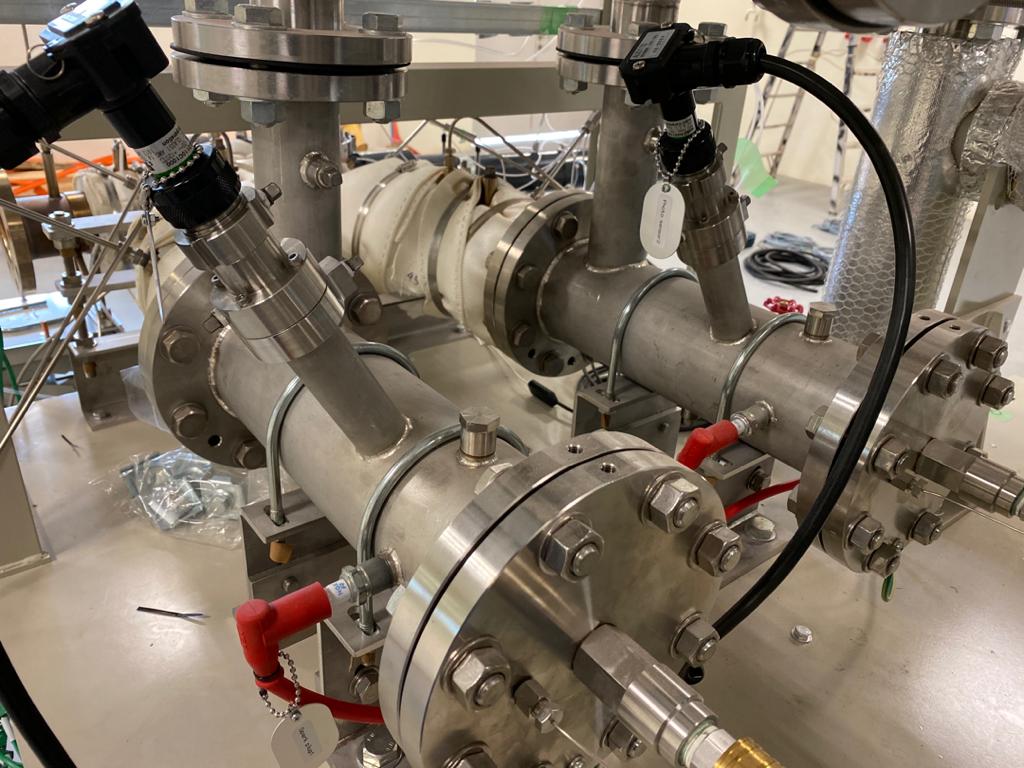
The Hot & Cold-Flow Steady State Turbocharger Test Facility supports turbocharger research at the Institute for Sustainable Transport (UTM IST) by providing controlled conditions for compressor and turbine performance studies. Two independent LPG combustors enable flexible hot-gas generation up to approximately 600 °C, while motorized valves regulate flow and multiple sensors capture pressure, temperature, speed, and vibration. Researchers can map single-entry and twin-scroll configurations, investigate variable-geometry and electrically assisted turbochargers, and study heat transfer, surge, reliability, and endurance. The facility helps turn repeatable test data into insights for more efficient boosting systems.
Built for Repeatable, Adaptable Testing
Automated Performance Mapping
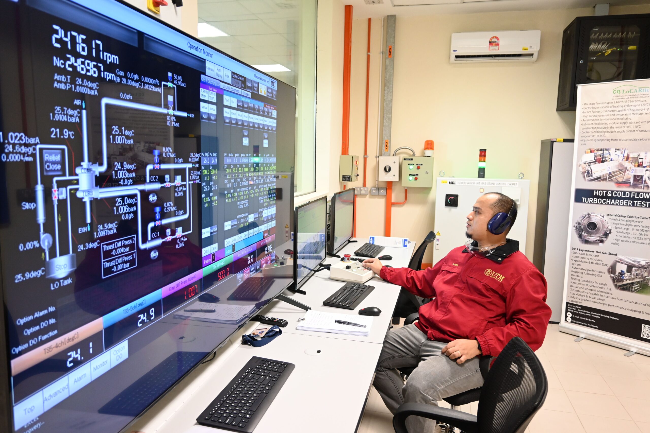
Generate ISO-standard turbocharger maps using target corrected speed and mass flow parameter (MFP), or target pressure ratio and corrected MFP.
Conditioned Lubricant and Coolant
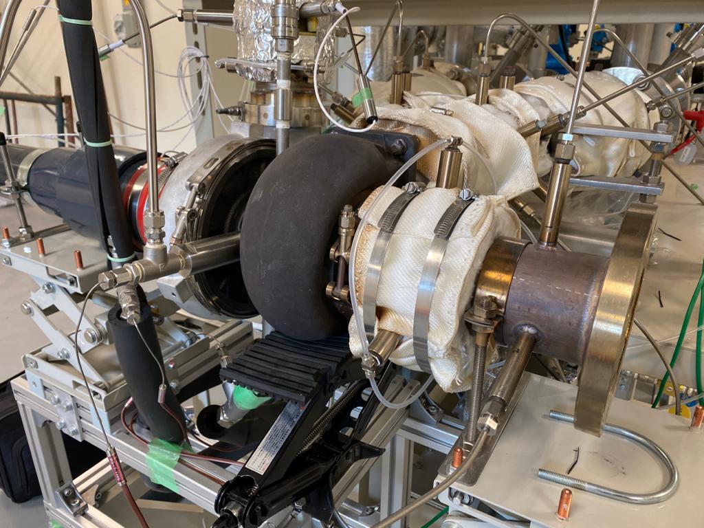
Dedicated conditioning modules help maintain defined oil and coolant conditions throughout steady-state tests.
Precision Control and Expandable Monitoring
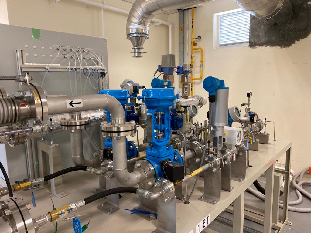
Motorized valve control, pressure and temperature measurements, speed sensing, and vibration detection support reliable data capture in a flexible, expandable monitoring system.
Hot & Cold-Flow Test Specifications
Flow and Gas Supply
Flow up to ~0.4 kg/s at 5 bar (±0.2%)
Hot-gas temperature up to ~600 °C
Two independent LPG combustors for flexible control
Turbocharger Operation
Turbocharger speed up to ~400,000 rpm (±0.25%)
Motorized valves for precise flow control
Hot- and cold-flow steady-state operation
Measurement and Monitoring
Multiple pressure measurement points
Multiple temperature measurement points
Accelerometer-based vibration detection
Control and Conditioning
Automated ISO-standard performance mapping
Lubricant and coolant conditioning modules
Expandable control and monitoring system
Steady-State Research
Mapping, Thermal and Durability Testing
Compressor and Turbine Mapping
Generate steady-flow performance maps for compressors and turbines, with automated testing by corrected speed and mass flow parameter or by pressure ratio and corrected mass flow parameter.
Thermal and Operational Testing
Investigate turbocharger heat transfer and thermal characteristics, evaluate reliability and endurance, and examine surge behavior under controlled test conditions.
Across Turbocharger Configurations
From Single-Entry Turbines to Advanced Boosting Systems
The facility supports steady-flow testing of single-entry turbochargers and double or twin-scroll turbines. Twin-scroll configurations can be evaluated under full, partial, equal and unequal admission conditions to reveal how flow distribution affects performance. Controlled operating conditions also enable studies of variable geometry turbochargers (VGT) and e-turbochargers, supporting comparison across conventional and advanced boosting technologies.

How Turbocharger Performance Mapping Works
Step 1
Define the test configuration and operating envelope, then condition the lubricant, coolant and hot-gas supply for steady-state measurements.
Step 2
For ISO-standard mapping, set a target corrected speed and mass flow parameter (MFP), or select a target pressure ratio (PR) and corrected MFP.
Step 3
Use motorized valve control to reach each target, stabilize the operating point and record flow, pressure, temperature, speed and vibration data.

